Home
> Capabilities & Expertise > MicrotensiometerSchematic
MicrotensiometerSchematic

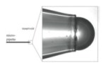
Fig. 1. Schematic diagram of the microtensiometer apparatus including convection. Parts include (A) microscope condenser, (B) peristaltic pump, (C) microtensiometer sample cell, (D) pressure transducer, (E) 3-way solenoid valve, (F) constant pressure head, (G) microscope objective for image analysis, (H) 21-gauge needles and (I) micropipette.
Comments (0)
Trackbacks (0)
Leave a comment
Trackback
